DOC 02WORKSPACES
World
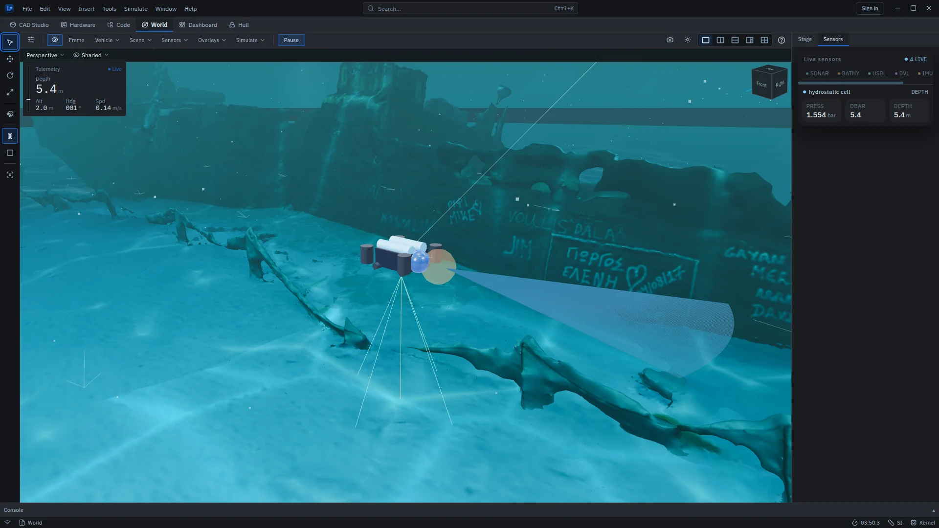
The World (Alt+4) is the 3D simulation: a vehicle running live in one of nine underwater scenes, with its sensors, overlays and any parts or hulls you have added, drawn in up to four views at once. It is where LEVIATHAN opens, and where the rest of the application becomes visible: the vehicle's state feeds the Dashboard, parts from CAD Studio and hulls from the Hull workspace appear here as solid objects, and episodes and replays play back here.
Layout
- Tool strip, left: Select, Move (W), Rotate (E), Scale (R), Snap, Play or Pause, Stop, and Frame the vehicle.
- Toolbar, top: view settings, grid, Frame, then the Vehicle, Scene, Sensors, Overlays and Simulate menus and Play; at the right, screenshot, Lighting, the five view layouts and the guides.
- Views, centre: one to four, each with a header holding its Camera and Display menus, Track vehicle, and Maximize.
- Dock, right: Stage (the scene tree and the Property panel) and Sensors (live sensor output).
Mouse: left-drag orbits, middle- or right-drag (or Shift-drag) pans, the wheel zooms. Click a face of the view cube to turn to it.
Views and cameras
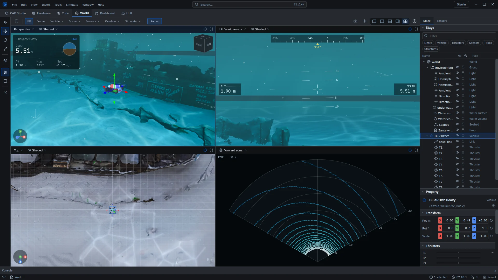
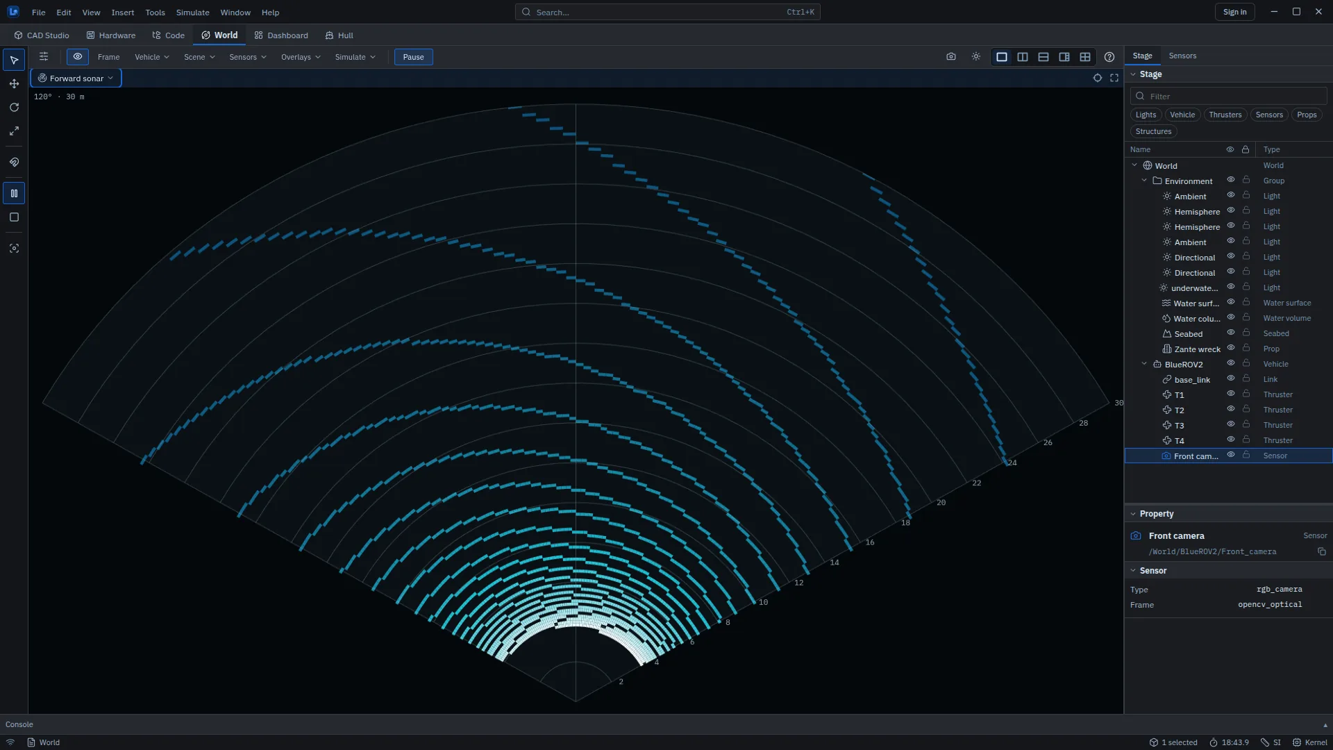
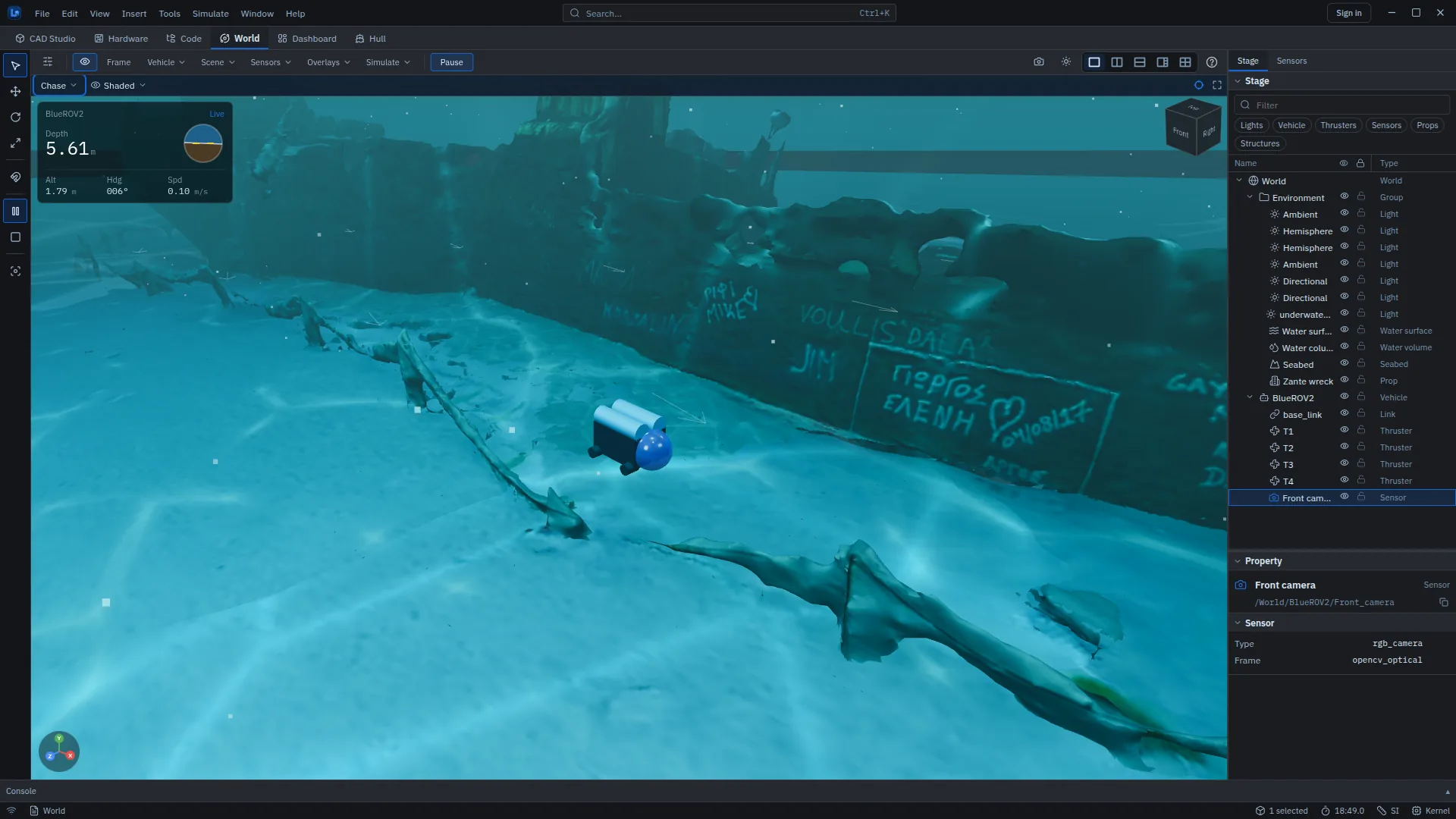
The layout buttons, or keys 1 to 5, choose Single view, Two views, side by side, Two views, stacked, One large + three or Four views. The four-view default shows Perspective, the vehicle's camera, Top and the forward sonar. Each project remembers its own layout.
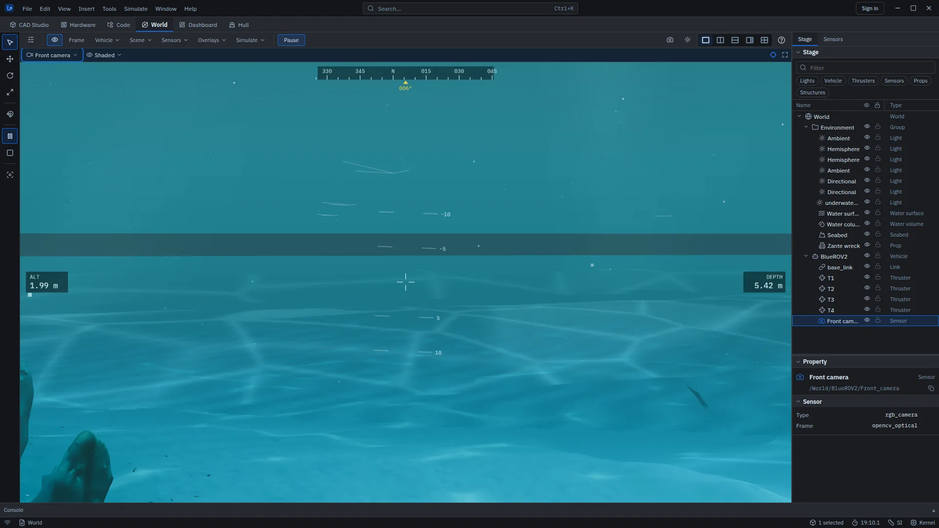
A view can look through any camera or sensor the vehicle declares, or follow it in a chase view.
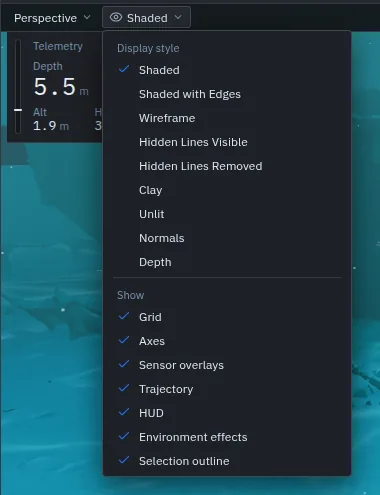
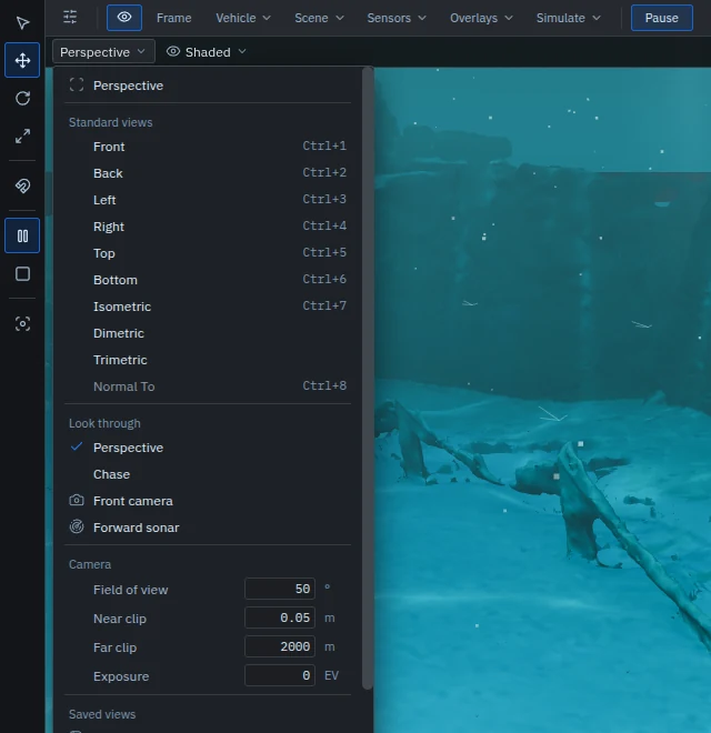
| Group | Entries |
|---|---|
| Projection | Perspective or orthographic |
| Standard views | Front, Back, Left, Right, Top, Bottom and Isometric (Ctrl+1 to Ctrl+7), Dimetric, Trimetric, Normal To (Ctrl+8, on a picked face) |
| Look through | Perspective, Chase (distance and height), each declared camera, Forward sonar |
| Sonar view | Range 10, 20, 30, 50 or 80 m; gain; Ocean, Grayscale or Amber colour map; 10 or 5 Hz; Freeze |
| Camera | Field of view 15–110°, near and far clip, exposure, section plane |
| Other | Save view (up to 20), Frame selection (F), Frame all (A), Link camera, Copy view as PNG, Maximize |
Toolbar menus
| Menu | Contents |
|---|---|
| Vehicle | Choose one of nine built-in vehicles; Upload CAD… (.glb, .gltf, .obj, .stl, .dae) with an axis convention; Import URDF / SDF / MJCF… to register a new vehicle |
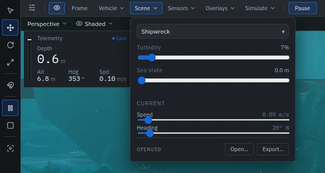
| Scene | Ocean preset (the nine scenes), turbidity 0–100 %, sea state (significant wave height 0–4 m), current speed 0–2 m/s and heading; OpenUSD open and export |
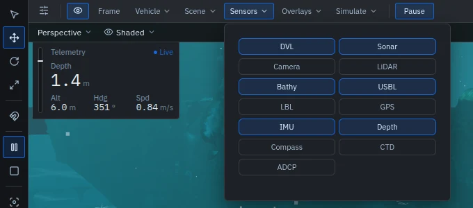
| Sensors | DVL, Sonar, Camera, LiDAR, Bathy, USBL, LBL, GPS, IMU, Depth, Compass, CTD and ADCP, all off until you turn them on |
| Overlays | Grid, Current, Velocity, Thrust, Buoyancy, Axes, Tether, Arm, Acoustic, Reef footprint |
| Simulate | Control mode Station-keep, Transit, Dive or Rollout; multi-vehicle Fleet and Formation; buoyancy-driven Glide |
| Lighting | Sun elevation and azimuth, exposure, brightness |
| View settings | Navigation speeds and inertia, selection colour, manipulator size and snap steps (0.1 m, 15°, 0.1), render scale, reset to defaults |
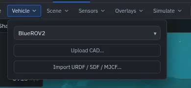 Vehicle
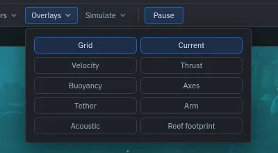 Overlays
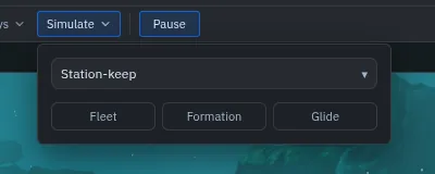 Simulate
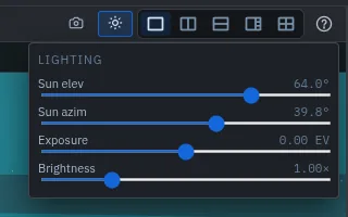 Lighting
Stage and Property
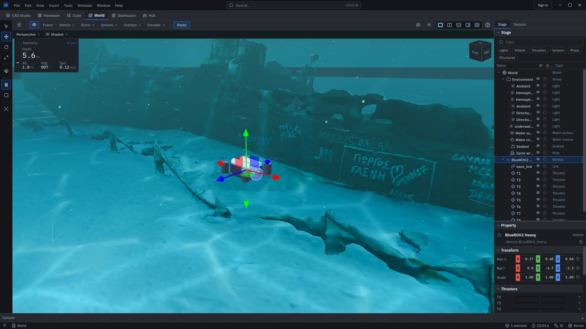
Stage is the scene tree: World ▸ Environment (lights, water surface, water column, current, seabed, props), the vehicle with its links, joints, thrusters and sensors, Structures (your parts and hulls) and Missions (the rollout path and evaluated trajectories). Each row has visibility and lock toggles and a type. Filter chips narrow the tree to Lights, Vehicle, Thrusters, Sensors, Props or Structures; arrows, F2, F, H, Delete and Ctrl+A work on it; the context menu frames, isolates, hides, renames and copies the prim path.
Property, below it, shows the selection: name, prim path and a transform with colour-coded X, Y and Z fields that can be typed or dragged, with reset; for the vehicle, its live depth, altitude, heading, speed and thruster commands; for a sensor, its type, frame and a once-a-second live sample. Ctrl+Z undoes edits (up to 100 steps).
The Sensors tab
The Sensors tab shows each enabled sensor's output as you fly: a chip per sensor (Sonar, Bathy, USBL, LBL, GPS, DVL, IMU, Depth, Compass, CTD, ADCP, forward-looking sonar, LiDAR), and under it the reading and its coverage settings. See Sensors for what each one models.
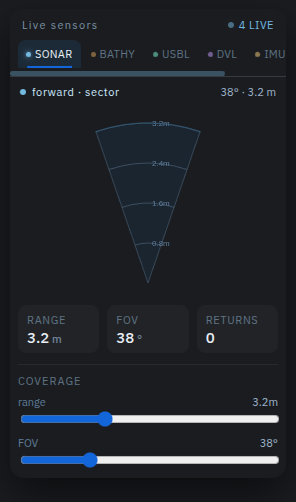 Sonar: sector, range and returns.
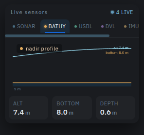 Bathy: nadir profile.
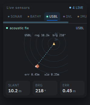 USBL: acoustic fix.
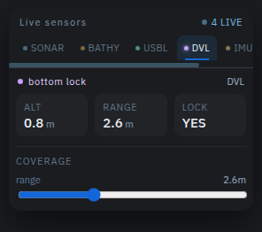 DVL: bottom lock.
Scenes and vehicles
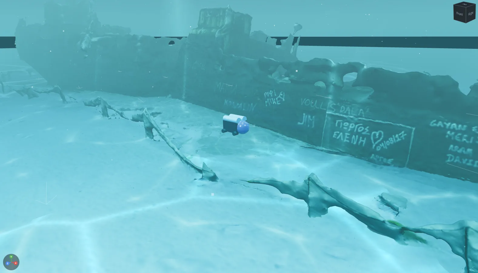
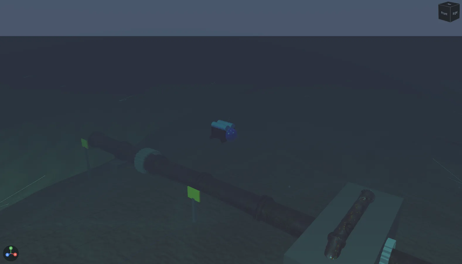
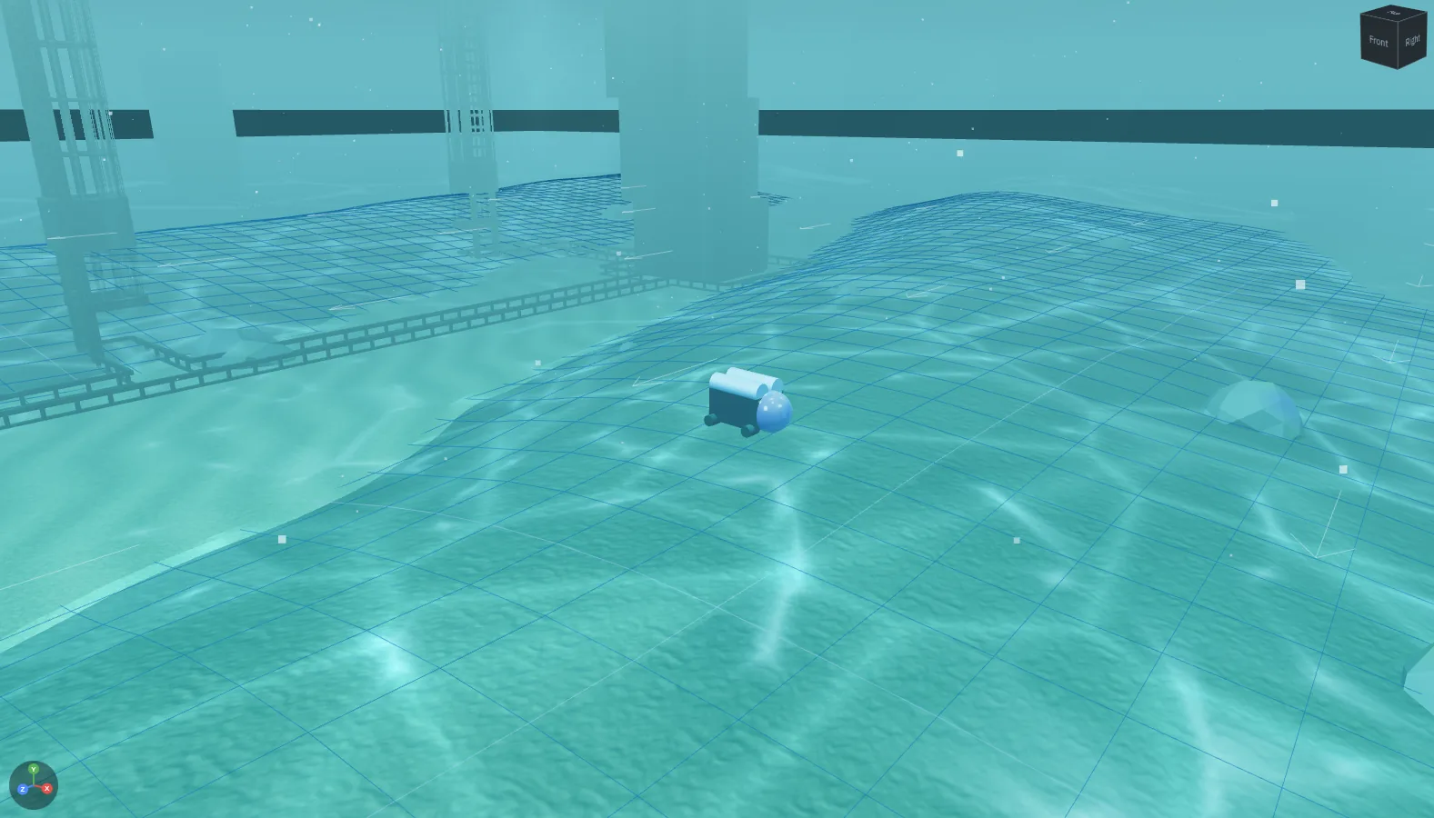
The nine scenes are Coral Reef, Shipwreck, Pipeline, Ice / Under-Ice, Dam / Reservoir, Offshore oil rig, Pier / Quay, Ship Hull and Harbour; each sets its own seabed, water, current and sound speed (see Environments). The nine vehicles are two inspection ROVs, a work-class ROV, three AUVs, a hovering AUV, a surface vessel and a glider (see Vehicles).
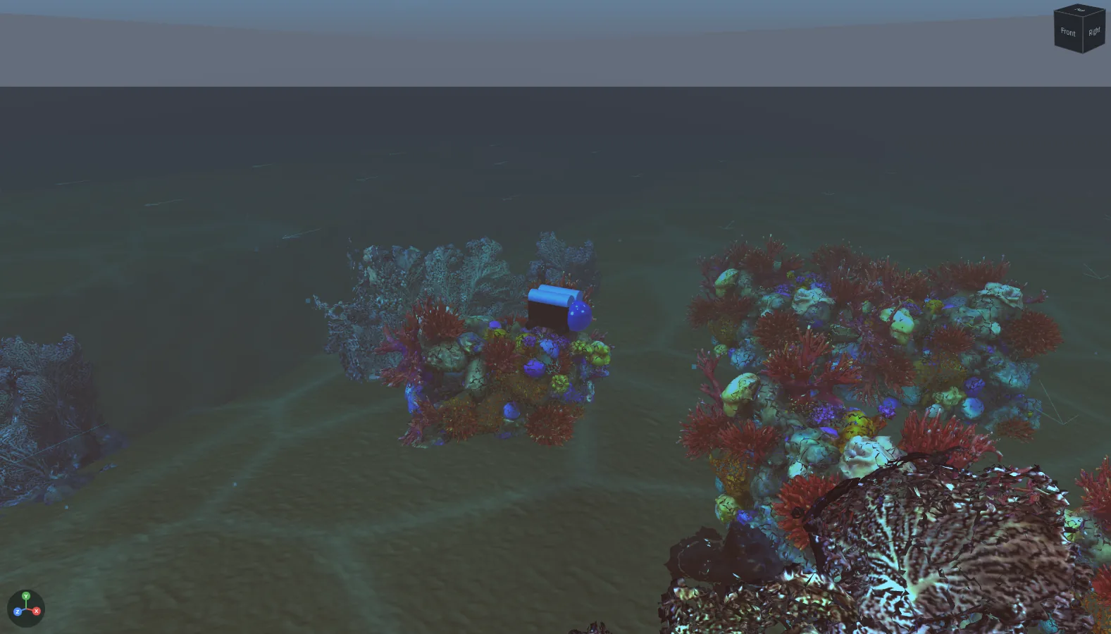
World assets
Parts from CAD Studio and hulls from the Hull workspace can be sent to the World as world assets. Each is placed at the first view's orbit target (a hull floats at its draft; other bodies rest on the seabed), appears under Stage ▸ Structures, can be moved, rotated, scaled and deleted, and is saved with the project.
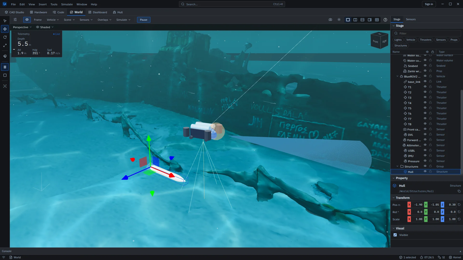
- Collision is generated as up to 32 convex pieces. Vehicles collide with them in simulation runs and live Worlds, and the World's sonar fan sees them.
- Limits: 64 MiB per asset, 400,000 triangles, 64 assets per project.
The convex pieces are larger than the body, so a hollow part is treated as filled in. The service's own sensor models, the scientific camera and the learning environments do not yet see world assets.
Commands and shortcuts
| Keys | Action |
|---|---|
| W, E, R | Move, rotate, scale the selection |
| F, A | Frame the selection, frame all |
| 1 – 5 | View layouts |
| Ctrl+1 – Ctrl+8 | Standard views, Normal To |
| Esc | Restore a maximized view |
| Ctrl+Z | Undo a scene edit |
View ▸ Show Performance Stats adds frame rate, frame time, draw calls and triangles to each view. File ▸ Capture view as PNG saves the view.