
DOC 02WORKSPACES
CAD Studio
CAD Studio is LEVIATHAN's parametric part modeller. It is built for the parts a marine robot needs: pressure housings, flanges, end caps, brackets and hulls. Geometry comes from a full boundary-representation (B-rep) solid-modelling kernel and a constraint solver for sketches, both bundled with the application. Parts can be measured, given a material, exported as STEP, STL or GLB, written out as a robot link in URDF or SDFormat, and sent to the World as solid objects the vehicle collides with.
Parts of this page marked Next release describe CAD Studio improvements that are finished and tested but not yet in the 0.8.0 download. They arrive with the next release:
- Work is never lost when a document is locked, taken over or recovered (Saving, revisions and recovery).
- Sweep corners can be kept sharp or turned into exact bends (Features).
- Export a body as a one-link URDF or SDFormat robot description (Robot links), and download any verified export.
- A wider material library for marine parts (Evaluate).
- Smooth shading, the model shown before its mesh, and faster recompute (Display and responsiveness).
- Ctrl+Z, Ctrl+Y and Ctrl+S in CAD Studio, and preview workspaces behind a setting (Preview workspaces).
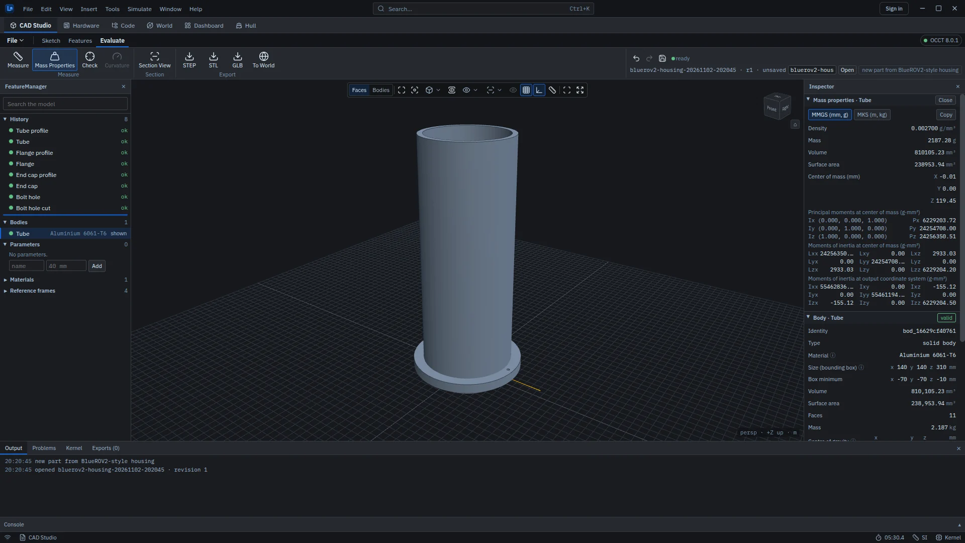
Layout
- Ribbon. A CAD File menu and three tabs: Sketch, Features and Evaluate. Only tools with a working implementation appear as buttons. Undo, redo, save, the kernel state (ready or recomputing), the document name and revision, and the last operation's message sit at its right end; the message's full history is in Output.
- FeatureManager, left: the model's history, bodies, parameters, materials and reference frames, with a search box. Drag the rollback bar between features, or focus it and use Up and Down; features below it are not computed. Right-click a feature for its context menu.
- View, centre: a heads-up toolbar with face and body selection filters, orientation, display style (shaded, shaded with edges and others) and section (off, or an X, Y or Z plane), plus a clickable view cube. Faces pre-highlight under the pointer.
- Inspector, right: the selected feature, body or face, and the Evaluate results.
- Dock, bottom: Output, Problems (recompute errors, blocked features, warnings and stale bodies), Kernel and Exports.
Documents and templates
A part is a native LEVIATHAN CAD document (.les), saved by revision with a SHA-256 of its content, and with an autosave that is offered back after an unexpected exit. File ▸ New from Template starts from one of four templates:
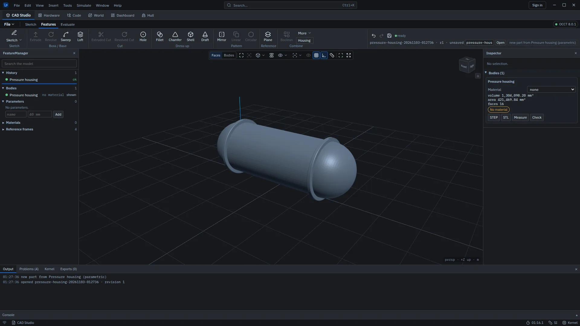
- Pressure housing (parametric): a cylindrical enclosure, 150 mm outside diameter, 6 mm wall, 300 mm long, with a hemispherical end cap.
- BlueROV2-style housing: a tube with flange, end cap and bolt-hole pattern (Figure 5.1).
- Torpedo AUV hull (Myring): an axisymmetric torpedo hull revolved from nose, body and tail parameters.
- Pressure housing calculator: preliminary wall and buckling estimates for a housing. Its results are estimates, not depth ratings.
File ▸ Import STEP / IGES / STL brings in outside geometry as the first feature of a new part, or adds it to the open one, as an Import base body. STEP and IGES are read in metres as written, and STL in millimetres. The limit is 64 MB or 200,000 triangles. An open STL mesh becomes a surface body, which has no volume or mass.
Document versions Next release
- Open only opens. Open (or Enter in the document field) opens a saved document and lists the saved ones to choose from; a mistyped name reports that there is no such document instead of creating an empty one. Create / open still creates.
- Documents stay readable by 0.8.0. A save keeps the format LEVIATHAN 0.8.0 reads whenever the document allows it, and an unchanged document saves byte for byte as before. Only a feature that 0.8.0 cannot read, such as a sweep with Bend corners, needs the newer format. Saving then asks you to Upgrade and save (or Cancel), and the previous revision is kept for older versions.
- Documents from a newer LEVIATHAN open read-only and are never changed: This document was saved by a newer LEVIATHAN … update LEVIATHAN to edit it.
- Opening a document never rewrites its revisions on disk.
Sketch
Sketches are solved by the built-in constraint solver. Sketch (Features tab) or Insert ▸ Sketch on starts a sketch on the XY, XZ or YZ plane, a reference plane or a selected face. Dimensions are typed at the cursor and accept expressions such as 40 mm, t + 5 or 90 deg; bare numbers are millimetres or degrees. A sketch is coloured by its state: blue when under-defined, white when fully defined, and red when over-defined by conflicting or redundant relations.
| Group | Tools |
|---|---|
| Entities | Line, rectangle, circle, arc, slot (click two centres), polygon (3–64 sides), spline (click fit points; click the first point to close) |
| Edit | Trim (cut at lines, circles and arcs), offset (a chain of lines, or circles; negative is inside), mirror (about the last selected construction line) |
| Relations | Automatic relations while drawing, plus midpoint, symmetric, concentric, fix and angle |
| Dimensions | Smart Dimension: a diameter on a circle, a radius on an arc, an angle between two lines |
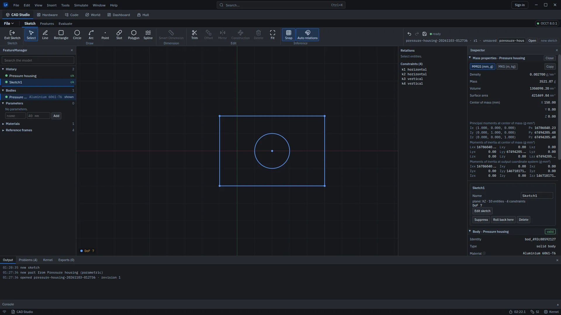
Rectangles add their horizontal and vertical relations; slots, polygons (inscribed in a construction circle) and splines (2–64 points) are built the same way. Snapping uses points and a grid, and lines within 3° of horizontal or vertical are inferred as such. Relations include coincident, horizontal, vertical, parallel, perpendicular, tangent, equal, distance, radius, diameter, angle, fix, on, midpoint, symmetric and concentric; a conflicting or redundant one is flagged. Enter ends a spline, Esc steps back to Select, and Delete removes the selection.
Features
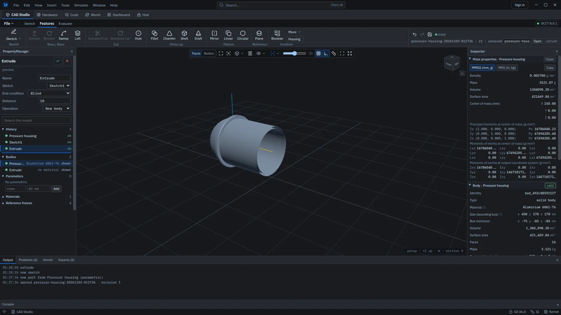
A feature opens in a PropertyManager. The feature is added as soon as its references are complete, so the preview is real kernel geometry. OK keeps it, and Cancel undoes every change made while it was open.
| Feature | Options |
|---|---|
| Extrude and Cut | Blind, blind reversed, mid-plane, through all, through all both ways; as a new body, or added to, cut from or intersected with a body |
| Revolve, Sweep, Loft | Sweep along a path of several curves keeps the section normal to the path. Next release Corners: Sharp (as drawn), the default, or Bend (exact elbows), which turns each sharp corner of the path into a smooth pipe bend with an editable Bend radius (by default 1.5 × the profile size, shown as auto; it must be larger than the profile). A loft section with holes is refused. |
| Hole Wizard | Hole, counterbore or countersink with ISO metric presets M2–M12 (ISO 273 normal clearance, ISO 4762 counterbore, ISO 10642 90° countersink); through all or blind |
| Fillet, chamfer, shell, draft | Edge and face modifiers |
| Pattern, mirror | Repeat or mirror features |
| Boolean | Union, subtract, intersect |
| Reference plane | Offset from the XY, XZ or YZ plane |
Named parameters can drive dimensions, so a housing's wall thickness or bore can be changed in one place.
Next release Cancel in a PropertyManager undoes only that feature's own changes; anything else you changed while it was open is kept, and Output says so.
A sweep whose path has sharp corners often cannot pass the STEP export check, because its re-imported shape differs from the model. The export is then refused and Problems suggests setting that sweep's Corners to Bend. CAD Studio never changes the shape by itself. Bend rounds every sharp corner, so the part's volume is a little smaller than the sharp version.
Evaluate
- Measure. Pick two faces for the minimum distance, the normal distance between parallel planes, the angle, and the centre distance between cylinders or spheres, together with each face's type, area, radius or diameter, and dX, dY and dZ.
- Mass Properties. In MMGS or MKS units: density, mass, volume, surface area, centre of mass, principal axes and moments at the centre of mass, moments of inertia at the centre of mass and at the output coordinate system. Products of inertia are ∫xy dm. Copy puts a text report on the clipboard. A body needs a material for mass, inertia and buoyancy; without one it shows No material.
- Check. Geometry validity: closed or free edges, invalid sub-shapes, short edges, maximum tolerance and unnamed faces. Curvature is shown for a selected face.
- Section View. Cut the view at the X, Y or Z plane and move the cut with the slider.
- Export. STEP, STL and GLB (glTF binary, metres, +Y up). Each export is read back and verified before it is recorded in the document's exports. Next release URDF and SDFormat robot links (see Robot links); a Download button on every entry in the Exports dock, which saves the file as <document>-<body>.<ext> after re-checking its SHA-256; finer STL and GLB meshes scaled to the part, so small curved parts export; and a refused export no longer replaces the last verified file.
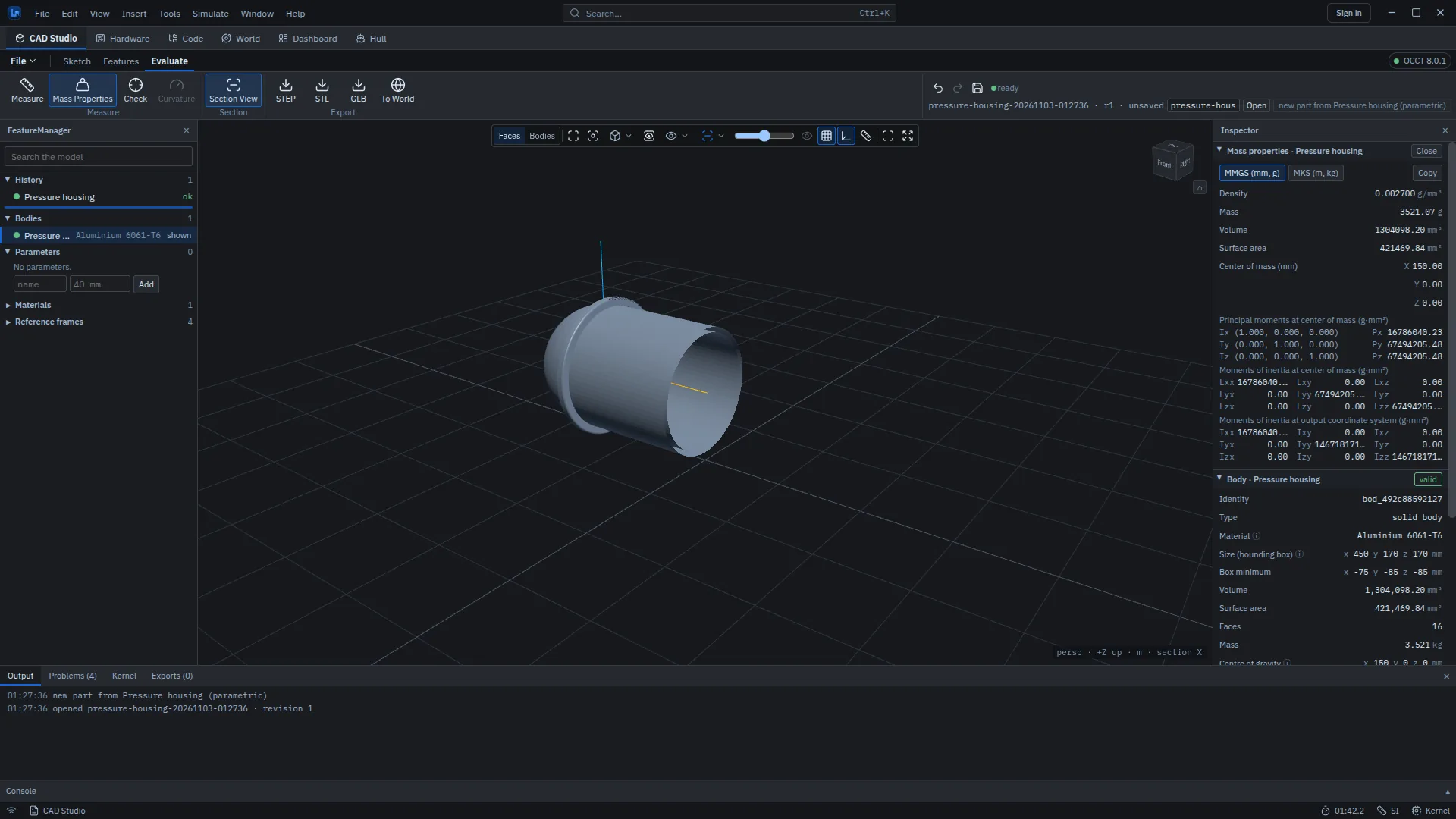
Materials: Aluminium 6061-T6, Titanium Ti-6Al-4V, Stainless steel 316, Acetal (POM-C) and Acrylic (PMMA). Their values are illustrative, not design allowables. A body's net buoyancy in sea water is shown with its mass.
Next release New material assignments choose from a library of nine marine materials, each with density, stiffness, strength and thermal values where they are known:
| Group | Materials |
|---|---|
| Aluminium | 6061-T6, 5083-H116 |
| Stainless steel | 316L, duplex 2205 |
| Titanium | Ti-6Al-4V Grade 5, annealed |
| Plastics | POM-C acetal, PMMA cast acrylic, PVC-U rigid |
| Buoyancy | Syntactic foam (compressive values and density only) |
Metal strengths are specification minimums and the other values are typical. They are not design allowables. Where a value is not known, such as Poisson's ratio for some of these materials, it is left empty rather than guessed. Existing documents keep the materials they were saved with, and the pressure housing calculator lists the new materials before the five illustrative ones.
Values are shown in millimetres with two decimals and thousands grouped, and mass in kilograms or grams. Values below 10−9 mm, which are kernel round-off, show as zero.
Robot links: URDF and SDFormat Next release
URDF and SDF buttons in Inspector ▸ Bodies, and File ▸ Export body as URDF (one link) or Export body as SDFormat (one link), write the selected body as one rigid robot link:
- its mass, centre of mass and full inertia tensor about the centre of mass, in SI units;
- in the robotics frame convention, x forward, y left and z up;
- with the body's verified STL as both its visual and collision mesh.
Each file is read back and compared with the CAD mass properties before it is recorded (Output: read back PASS), and appears in the Exports dock with Download. The buttons are disabled until the body has a material: a robot link needs a mass and an inertia, and LEVIATHAN never guesses a density.
Vehicle Import accepts these files and other URDFs. It uses the declared mass, centre of mass and inertia, combined across the URDF's joints, and puts the body origin at the declared centre of mass. The result shows Inertia … (declared) or (estimated), with a warning line whenever something was estimated or dropped: estimated inertia, a mesh-only hull, no declared centre of mass, a mass override or dropped products of inertia. A physically impossible inertia tensor is refused.
Assemblies with several links and joints, MJCF and hydrodynamic coefficients are not exported yet.
Export to World
Evaluate ▸ To World (or File ▸ Export body to World) sends the selected body to the World workspace as a world asset. The Hull workspace does the same for a hull with Export ▸ To World.
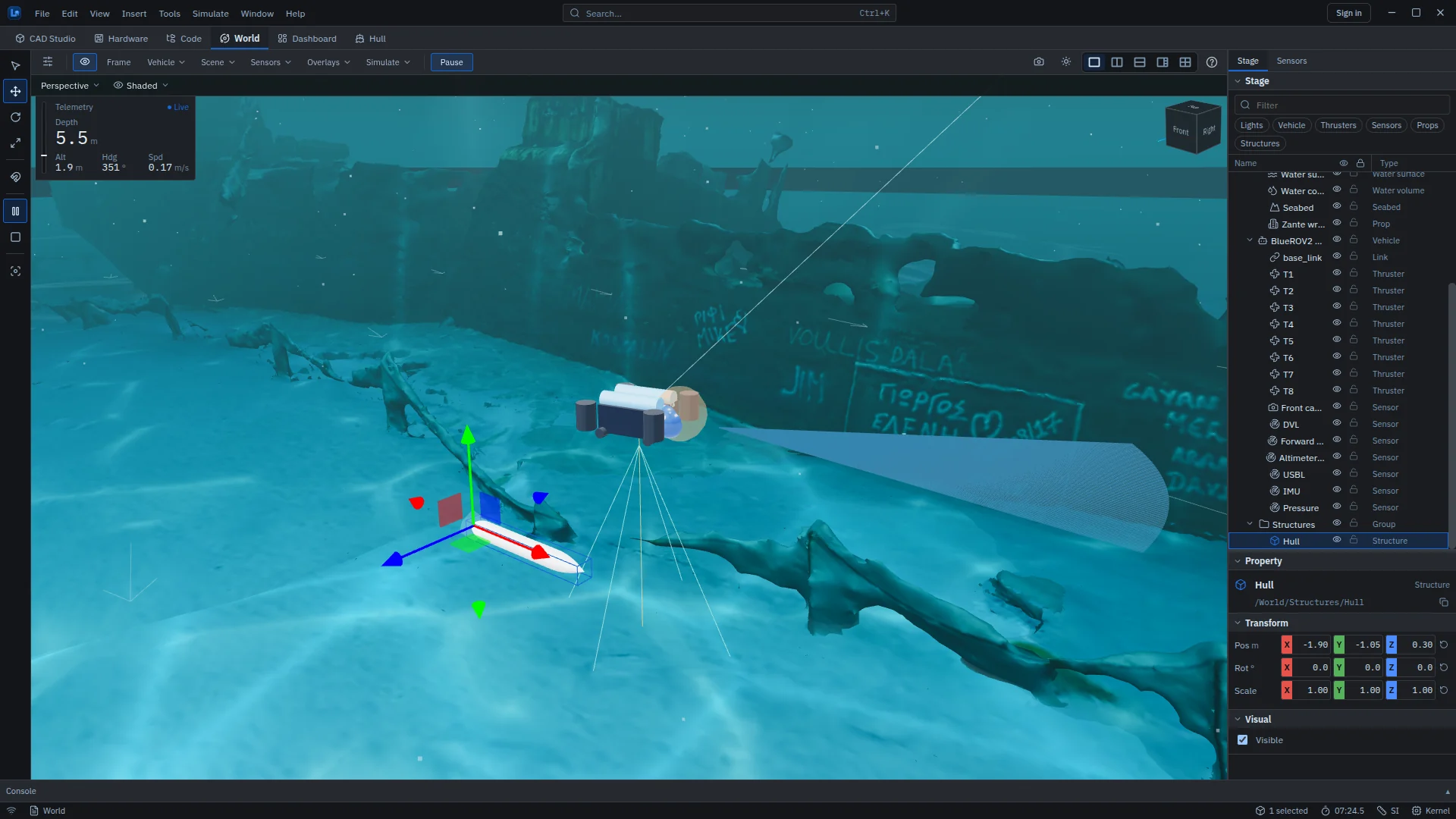
- The mesh is stored with the open project, or with the application's own World when no project is open, and is reloaded when the project opens.
- Its collision is generated as convex pieces. Vehicles collide with it in simulation runs and in live Worlds.
- It is placed at the World view's orbit target. A hull floats at its draft; other bodies rest on the seabed when the target is below it.
- Move, rotate or scale it with the gizmo or in Property; changes are saved. Delete it from the Stage with Delete or the context menu.
The convex pieces cover the body and are larger than it: a hollow part, such as an open housing, is filled in. The World computes contact with these pieces but no hydrodynamics for the asset itself.
Display and responsiveness Next release
- Smooth shading. Curved faces such as cylinders, fillets and hulls are shaded with the exact surface normals from the kernel, and edges between faces stay sharp. The display mesh is finer on small parts and never coarser than 0.1 mm.
- Model first, mesh after. After an edit the feature tree, validity and mass properties update at once, and the 3D mesh follows a moment later. Meanwhile the view shows Updating mesh… with the previous shape dimmed, and clicks select nothing, so you never pick a face that has moved.
- Faster recompute. Features whose inputs have not changed are reused instead of rebuilt, so editing late in a long history recomputes only what follows the edit.
- Section views pick only the faces you can see.
- The status chip shows ready, applying, recomputing or meshing, and the kernel chip shows Kernel busy while the kernel works through other requests.
Preview workspaces Next release
File ▸ Show preview workspaces, off by default, adds the Assembly, Marine and Drawing workspaces as tabs, each labelled Preview. They work, but each has documented limits. The setting is remembered for you on this computer; turn it off and the tabs go away, and if you were in one, CAD Studio returns to Features.
The geometry kernel
The geometry kernel runs as a separate process, which the application bundles and starts itself, so there is nothing to install. Its state is shown in the status bar (Kernel, Kernel starting, Kernel unavailable) and in the chip at the top right of CAD Studio, whose popover offers Retry. If the kernel is unavailable, CAD Studio says so and geometry operations wait until it is back.
Next release GET /api/cad/capabilities reports what this version of CAD Studio supports: document format versions, the maturity of each feature, limits and what is not modelled. It answers without starting the kernel.
Saving, revisions and recovery
- Every save writes a new revision with a SHA-256 of its content. The first revision, named revisions, the sources of exports and the newest 100 are kept.
- Exports are re-read and verified before they are recorded, and are kept with the document.
- Autosave is offered back after an unexpected exit (Recover or Set aside).
- One writer at a time: a document already open elsewhere opens read-only.
Locked documents and unsaved work Next release
- Read-only, with the reason. When another session is editing the document, a banner says so, with how long ago it was last active, and offers Check again.
- Take over a stale lock. When the session holding the document has gone (its process ended, the computer restarted, or it stopped responding for two minutes), the banner also offers Take over…. Taking over is never automatic: you confirm it, the previous session can no longer save, and its unsaved changes are copied to autosave-backups/ in the document folder before anything is written.
- Recover or set aside. Unsaved work then shows as Unsaved work found · autosaved <time> with Recover and Set aside. Editing is paused until you choose, and work you set aside stays on disk in autosave-discarded/.
- Autosave first. Every change is autosaved before it is applied. If the autosave cannot be written, the change is not made and CAD Studio says so.
- Named versions. Save as named version with nothing changed now names the current revision. A revision that an export was made from is always kept.
View keys
| Keys | Action |
|---|---|
| F, S | Fit all, focus the selection |
| 1, 3, 7, 0 | Front, right, top, isometric |
| Ctrl+1, Ctrl+3, Ctrl+7 | Back, left, bottom |
| 5 | Perspective or orthographic |
| Ctrl+Z, Ctrl+Y or Ctrl+Shift+Z | Undo, redo (the same commands as Edit ▸ Undo and Redo; inside a text field they edit the text) |
| Ctrl+S | Save Next release |